How Do I Map a Flat Structure Containing Both Header and Line Records to a Hierarchical XML? (Magic xpi 3.x)
When working with the Data Mapper in Magic xpi, you might find yourself in a situation where you need to map a flat structure to a hierarchical XML file.
Mapping a flat structure to a hierarchical XML file:
After you have dragged a Data Mapper into the Studio’s flow area, the first thing you need to do is to configure the Data Mapper’s Source properties, as follows:
-
In the Data Mapper Configuration dialog box, click Configuration.
-
In the Source/Destination Management window, click New on the Source side. Set the Source’s Type as XML.
-
Click Properties on the Source side.
-
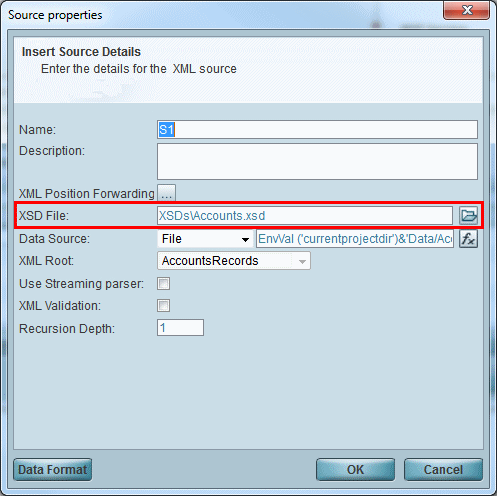
In the Source Properties window’s XSD File parameter, click the  button and select the required XSD file (in this case, Accounts.xsd).
-
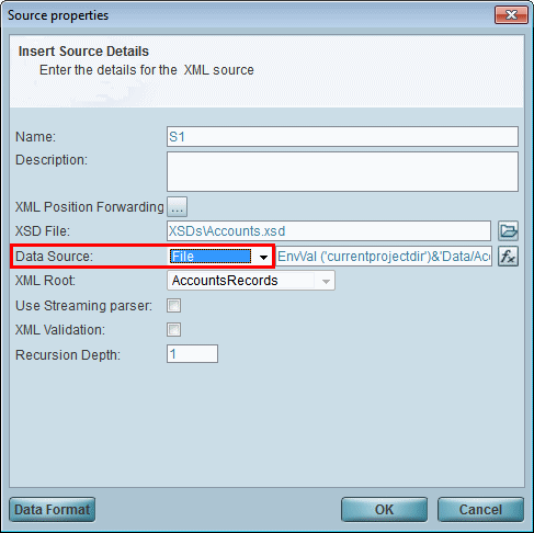
You need to define where you will take the data from, which, in this case, is a file called Accounts.xml. In the Data Source parameter, select File from the drop-down list.
-
Open the Expression Editor with the  button, and enter the following expression: EnvVal ('currentprojectdir')&'Data/Accounts.xml'

This expression tells the Source to look for a data file called Accounts.xml in the current project directory.
-
Click OK to close the Expression Editor, followed by the Source Properties window.
After you have finished configuring the Data Mapper’s Source properties, you need to configure the Destination properties, as follows:
-
In the Source/Destination Management window, click New on the Destination side. Set the Destination’s Type as XML.
-
Click Properties on the Destination side.
-
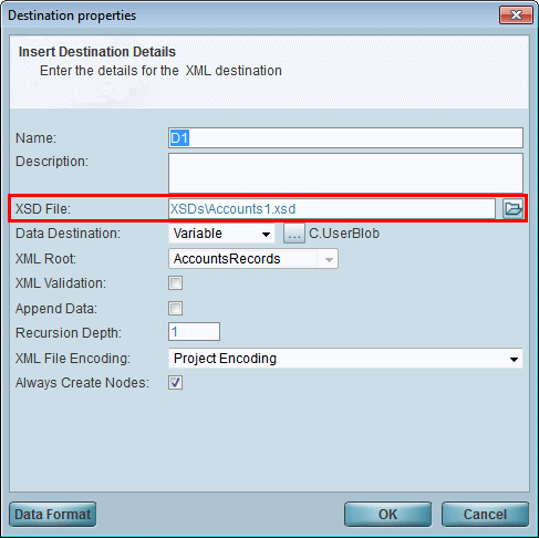
In the Destination Properties window’s XSD File parameter, click the  button and select the required XSD file (in this case, Accounts1.xsd).
-
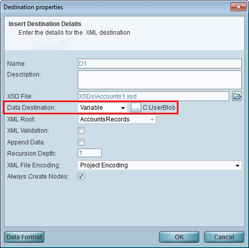
In the Data Destination parameter, select Variable from the drop-down list. Click the  button and select C.UserBlob. This is where the mapped data will be sent to.
-
Click OK to close the Destination Properties window.
Now, to get a clearer picture of the data, let’s take a closer look at the structures of the Accounts.xsd and the Accounts1.xsd files as displayed in the Data Mapper window. You access this window by clicking Map in the Source/Destination Management window.
In the Source pane (as shown below, left), you can see a flat structure defined by the contents of the Accounts.xsd file. This comprises a compound node called Account, which is made up of Name and ID nodes. In addition, there is a sibling compound node called PhoneNumber, which is made up of primary, value and accountID nodes.
Note that there is no parent-child relationship between the two compound nodes. The only connection between them is via the ID node and the accountID node.
In the Destination pane (as shown below, right), you can see a hierarchical parent-child structure defined by the Accounts1.xsd file. This comprises a parent compound node called Account, which is made up of Name and ID nodes. In addition, there is a child compound node called PhoneNumber, which is made up of primary and value nodes. In this case, the accountID node is unnecessary because the relationship between the accounts and their phone numbers is governed by the structure of the schema.
Next, you need to map the Source data to the Destination data, as follows:
-
In the Source/Destination Management window, click Map to open the Data Mapper window.
-
In the Source pane, right-click on the Account compound node and select Connect All. Then drag the mouse to the Account compound node in the Destination pane, and click. These compound nodes, along with their Name and ID simple nodes, will then be seen as connected in the Data Mapper window (as shown below).
-
In the Source pane, right-click on the PhoneNumber compound node and select Connect All. Then drag the mouse to the PhoneNumber compound node in the Destination pane, and click. These compound nodes, along with their primary and value simple nodes, will then be seen as connected in the Data Mapper window (as shown below).

The problem with this mapping is that each account will then hold the phone numbers of all the other accounts in addition to its own phone number. This happens because no filters have been applied to the mapping. To prevent this from happening, you should create the required filters:
-
Open the Variables for Flow dialog box (Flow menu > Variables) and create a flow variable called F.accountID.
-
To make sure that each account holds only its own phone number and not any others, you should use the Compound Level Computation mechanism. To do this, right-click on the Accounts compound node in the Destination pane and select Properties.
-
In the Node Properties dialog box, select the Advanced tab. Here, click New to create a new line.
-
In the Variable Name column, click the  button and select your F.accountID variable.
-
In the Expression column, click the  button to open the Expression Editor. Click the
  button and select the correct path for the ID node from the list.

The result of this expression is that, on the Source side, each iteration of the Accounts is given the value of the ID field.
Next, you need to filter the Source’s PhoneNumber records so that only those records with the same ID as the Destination’s Account will be sent to the child PhoneNumber record under that specific account:
-
Right-click on the PhoneNumber compound node in the Destination pane and select Properties.
-
In the Node Properties dialog box, select the General tab.
-
In the Execute Condition section’s Condition parameter, click the  button to open the Expression Editor. Click the
  button and select the correct path for the accountID node from the list.

Note that F.accountID is the flow variable that you created earlier for the purpose of holding the account’s ID.
-
Click OK to close the Expression Editor, followed by the Destination’s Node Properties window, the Data Mapper window, and the Data Mapper Configuration screens.
-
Set a breakpoint, and then debug the flow by right-clicking on the flow in the Navigation pane and selecting Debug.
-
Run your project by clicking the  Run/Continue Project button on the toolbar.
-
Click the  Context View button on the toolbar to open the Context View window.
-
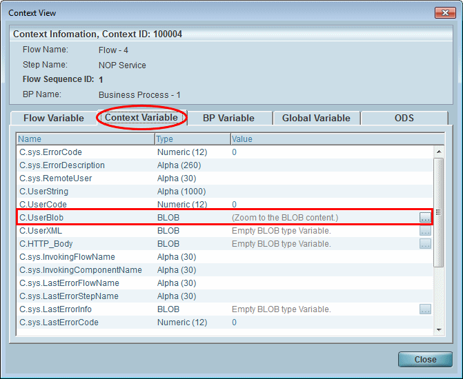
Here, select the Context Variable tab and look in the Name column for the C.UserBlob variable. Remember that you previously selected this variable in the Destination Properties dialog box’s Data Destination parameter to hold the results data. Click the  button to zoom to the BLOB’s content.
-
In the View Variable: C.UserBlob window, select TXT from the drop-down list and click Open to see the actual XML file that you just created.
-
In the ContextView_BLOB.TXT XML file, you can see that each account has its own dedicated phone numbers listed underneath the account’s entry.
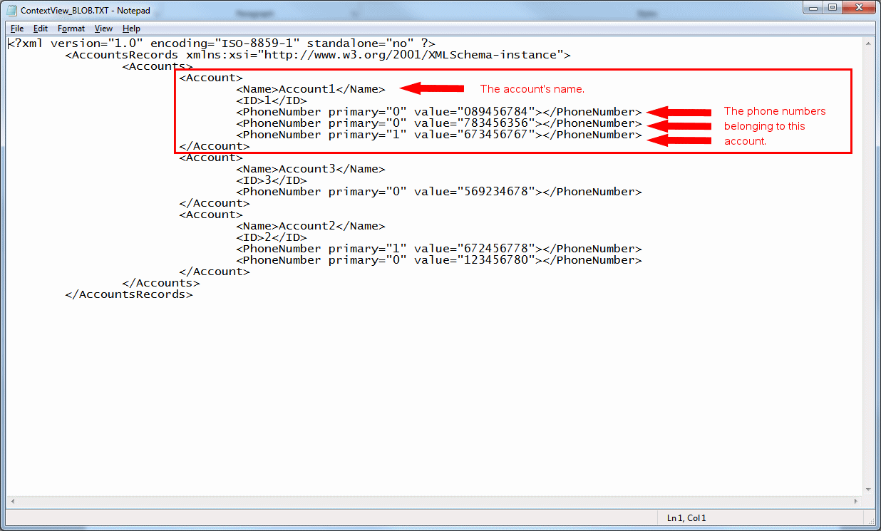
This XML was created in the following way:
-
For each Source Account element, an Account element was created in the Destination pane.
-
After that, the PhoneNumber elements were created in the Destination pane.
-
The phone numbers were then assigned to the accounts.
-
However, the filter that you created only mapped those phone numbers that matched the account ID to the Destination elements. This means that each account received only its own phone number(s), and not all the numbers contained in the Source file.

